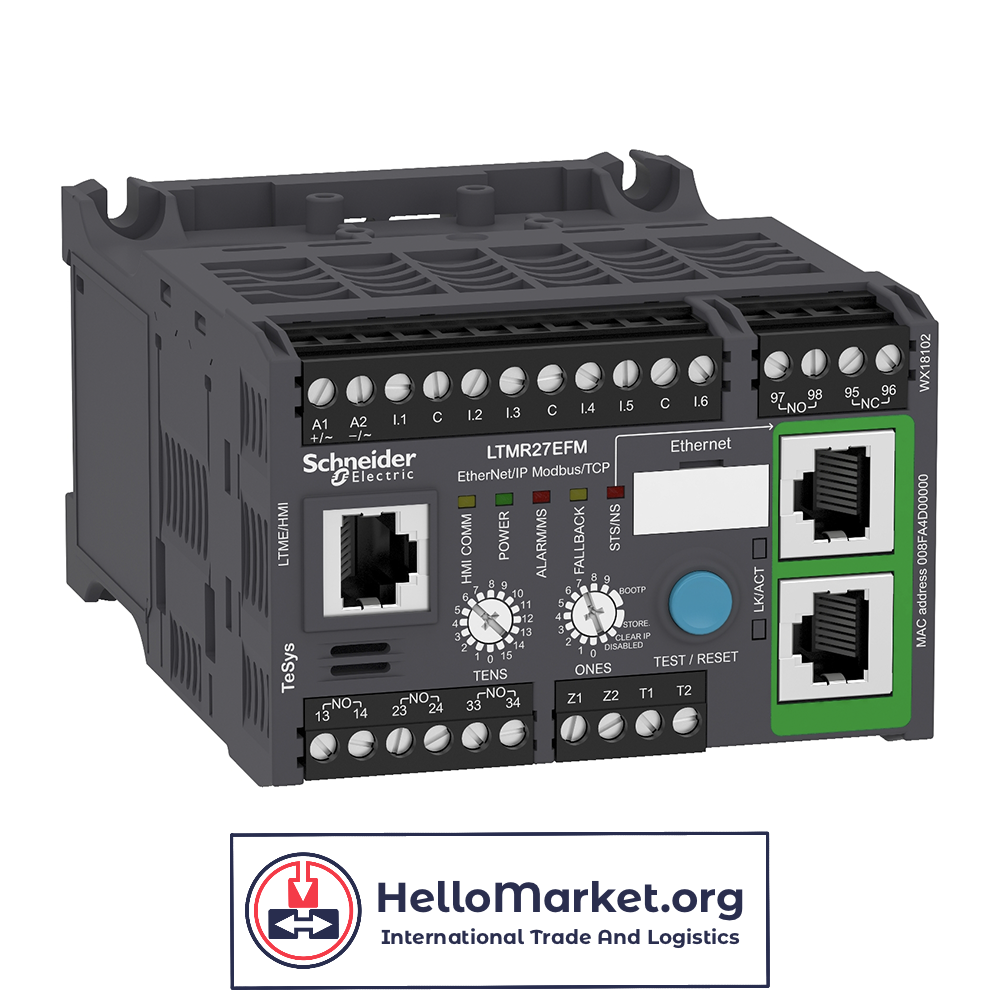
Schneider LTMR27EFM
$ 921,00 Request exact price
Terms of sale:
- Price Without Shipping:
Our prices are listed without shipping costs. Shipping charges will be calculated and added during checkout based on your location and preferred shipping method. - Price Variability:
Please note that prices are not fixed and may change due to factors such as market fluctuations, supplier costs, or promotional offers. - Worldwide Delivery:
We offer delivery to almost any country worldwide. During checkout, you can select your country for shipping options and associated costs. - These terms ensure transparency and flexibility in pricing and shipping options for our customers across the globe.
Description
buy Schneider
| Range | TeSys |
|---|---|
| Product name | TeSys T |
| Device short name | LTMR |
| Product or component type | Motor controller |
| Device application | Equipment monitoring and control |
| Measurement current | 1.35…27 A |
| [Us] rated supply voltage | 100…240 V AC 50/60 Hz |
| Current consumption | 8…62.8 mA |
| Supply voltage limits | 93.5…264 V AC |
| communication port protocol | Modbus TCP/EtherNet/IP |
| Bus type | Ethernet IEEE 802.3 0…159 10…100 Mbit/s, RJ45 2 shielded twisted pairs |
| [Ui] rated insulation voltage | 690 V EN/IEC 60947-1 690 V CSA C22.2 No 14 690 V UL 508 |
|---|---|
| [Uimp] rated impulse withstand voltage | 4 kV supply, inputs and outputs EN/IEC 60947-4-1 6 kV current or voltage measurement circuit EN/IEC 60947-4-1 0.8 kV communication circuit EN/IEC 60947-4-1 |
| Short-circuit withstand | 100 kA EN/IEC 60947-4-1 |
| Associated fuse rating | 4 A gG output 0.5 A gG control circuit |
| Protection type | Phase unbalance Earth-leakage protection Thermal protection Reverse polarity protection Power factor variation Overload Load fluctuation Locked rotor Thermal overload protection Phase failure Overload (long time) |
| Network and machine diagnosis type | Event recording Trip context information Phase fault and earth fault trip counters Trip history information Waiting time after overload tripping Fault recording Remaining operating time before overload tripping Starting current and time Motor control command recording Running hours counter/operating time |
| logic input number | 6 |
| Input current | 3.1 mA 100 V 7.5 mA 240 V |
| Current state 0 guaranteed | Logic input 0…40 V <= 15 mA 25 ms |
| Current state 1 guaranteed | Logic input 79…264 V >= 2 mA 25 ms |
| maximum output switching frequency | 2 Hz |
| Load current | 5 A 250 V AC logic output 5 A 30 V DC logic output |
| Permissible power | 480 VA AC-15), Ie = 2 A, 500000 cycles output) 30 W DC-13), Ie = 1.25 A, 500000 cycles output) |
| Maximum operating rate | 1800 cyc/h |
| Contacts type and composition | 1 NO + 1 NC fault signal 3 NO |
| Metering type | Average current Iavg Phase current I1, I2, I3 RMS Imbalance current Earth-fault current Temperature |
| Measurement accuracy | 5…15 % earth fault current internal measurement 1 % voltage 100…830 V) 3 % power factor 5 % earth fault current external measurement +/- 30 min/year internal clock 0,02 temperature 1 % current 5 % active and reactive power |
| Overvoltage category | III |
| Connection pitch | 0.20 in (5.08 mm) |
| Connections – terminals | Control circuit connector 1 0.00…0.00 in² (0.25…2.5 mm²) AWG 24…AWG 14)flexible with cable end Control circuit connector 1 0.00…0.00 in² (0.2…2.5 mm²) AWG 24…AWG 14)flexible without cable end Control circuit connector 1 0.00…0.00 in² (0.25…2.5 mm²) AWG 24…AWG 14)flexible without cable end Control circuit connector 1 0.00…0.00 in² (0.2…2.5 mm²) AWG 24…AWG 14)solid without cable end Control circuit connector 2 0.00…0.00 in² (0.2…1 mm²) AWG 24…AWG 14)flexible with cable end Control circuit connector 2 0.00…0.00 in² (0.2…1.5 mm²) AWG 24…AWG 14)flexible without cable end Control circuit connector 2 0.00…0.00 in² (0.5…1.5 mm²) AWG 24…AWG 14)flexible without cable end Control circuit connector 2 0.00…0.00 in² (0.2…1 mm²) AWG 24…AWG 14)solid without cable end |
| Tightening torque | Control circuit 4.43…5.31 lbf.in (0.5…0.6 N.m) flat 0.12 in (3 mm) |
| Pollution degree | 3 |
| Electromagnetic compatibility | Electrostatic discharge, 3 8 kV air, 6 kV contact)EN/IEC 61000-4-2) Radiated RF fields, 3 10 V/m)EN/IEC 61000-4-3) Fast transients immunity test, level 3 2 kV)EN/IEC 61000-4-4) Fast transients immunity test, level 4 4 kV)EN/IEC 61000-4-4) Voltage dips and interruptions immunity test 70 %, 500 ms)EN/IEC 61000-4-11) Conducted RF disturbances 10 V)EN/IEC 61000-4-6) Surges 0.5 kV)EN/IEC 61000-4-5) Surges 1 kV)EN/IEC 61000-4-5) Surges 1 kV)EN/IEC 61000-4-5) Surges 2 kV)EN/IEC 61000-4-5) Surges 2 kV)EN/IEC 61000-4-5) Surges 4 kV)EN/IEC 61000-4-5) Surges 2 kV)EN/IEC 61000-4-5) |
| Width | 3.58 in (91 mm) |
| Height | 2.40 in (61 mm) |
| Depth | 4.82 in (122.5 mm) |
| Net weight | 1.17 lb(US) (0.53 kg) |
| web services | Web server |
| Compatibility code | LTMR |
| Standards | IACS E10 UL 508 IEC 60947-4-1 EN 60947-4-1 CSA C22.2 No 14 |
|---|---|
| Product certifications | EAC DNV BV C-Tick CCC ABS RINA RMRoS CSA NOM LROS (Lloyds register of shipping) UL KERI GL ATEX |
| Protective treatment | 12 x 24 hour cycles EN/IEC 60068-2-30 48 h EN/IEC 60070-2-11 TH EN/IEC 60068 |
| Fire resistance | 1202 °F (650 °C) EN/IEC 60695-2-12 1760 °F (960 °C) UL 94 |
| Ambient air temperature for operation | -4…140 °F (-20…60 °C) |
| Ambient air temperature for storage | -40…176 °F (-40…80 °C) |
| Operating altitude | <= 2000 m without derating |
| Mechanical robustness | Vibrations mounted on symmetrical rail1 Gn, 5…300 Hz EN/IEC 60068-2-6 Vibrations plate mounted4 Gn, 5…300 Hz EN/IEC 60068-2-6 Shocks half sine wave acceleration15 Gn for 11 ms EN/IEC 60068-2-27 |
| IP degree of protection | IP20 |
| Unit Type of Package 1 | Db |
|---|---|
| Number of Units in Package 1 | 1 |
| Package 1 Height | 2.83 in (7.2 cm) |
| Package 1 Width | 3.94 in (10.0 cm) |
| Package 1 Length | 5.31 in (13.5 cm) |
| Package 1 Weight | 18.69 oz (530.0 g) |
| Unit Type of Package 2 | S02 |
| Number of Units in Package 2 | 10 |
| Package 2 Height | 5.91 in (15.0 cm) |
| Package 2 Width | 11.81 in (30.0 cm) |
| Package 2 Length | 15.75 in (40.0 cm) |
| Package 2 Weight | 12.38 lb(US) (5.615 kg) |
| Warranty | 18 months |
|---|