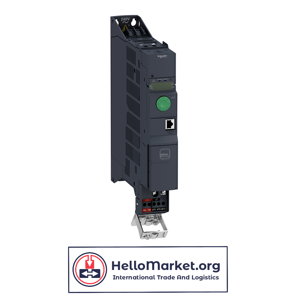
Schneider ATV31H037N4A
$ 207,00 Request exact price
Terms of sale:
- Price Without Shipping:
Our prices are listed without shipping costs. Shipping charges will be calculated and added during checkout based on your location and preferred shipping method. - Price Variability:
Please note that prices are not fixed and may change due to factors such as market fluctuations, supplier costs, or promotional offers. - Worldwide Delivery:
We offer delivery to almost any country worldwide. During checkout, you can select your country for shipping options and associated costs. - These terms ensure transparency and flexibility in pricing and shipping options for our customers across the globe.
Description
| range of product | Altivar |
|---|---|
| Product or component type | Variable speed drive |
| Product specific application | Simple machine |
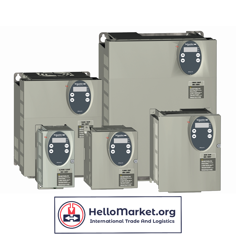
| Component name | ATV31 |
| Assembly style | With heat sink |
| variant | With drive order potentiometer |
| EMC filter | Integrated |
| [Us] rated supply voltage | 380…500 V – 5…5 % |
| Supply frequency | 50…60 Hz – 5…5 % |
| Network number of phases | 3 phases |
| Motor power kW | 0.37 kW 4 kHz |
| Motor power hp | 0.5 hp 4 kHz |
| Line current | 1.7 A at 500 V 2.2 A at 380 V, Isc = 1 kA |
| Apparent power | 1.5 kVA |
| Prospective line Isc | 1 kA |
| Nominal output current | 1.5 A 4 kHz |
| Maximum transient current | 2.3 A for 60 s |
| Power dissipation in W | 32 W at nominal load |
| Asynchronous motor control profile | Factory set : constant torque Sensorless flux vector control with PWM type motor control signal |
| Analogue input number | 4 |
| Product destination | Asynchronous motors |
|---|---|
| Supply voltage limits | 323…550 V |
| Network frequency | 47.5…63 Hz |
| Output frequency | 0.0005…0.5 kHz |
| Nominal switching frequency | 4 kHz |
| Switching frequency | 2…16 kHz adjustable |
| Speed range | 1…50 |
| Transient overtorque | 150…170 % of nominal motor torque |
| Braking torque | <= 150 % during 60 s with braking resistor 100 % with braking resistor continuously 150 % without braking resistor |
| Regulation loop | Frequency PI regulator |
| Motor slip compensation | Adjustable Suppressable Automatic whatever the load |
| Output voltage | <= power supply voltage |
| Electrical connection | Al1, Al2, Al3, AOV, AOC, R1A, R1B, R1C, R2A, R2B, LI1…LI6 terminal 2.5 mm² AWG 14 L1, L2, L3, U, V, W, PA, PB, PA/+, PC/- terminal 2.5 mm² AWG 14 |
| Tightening torque | Al1, Al2, Al3, AOV, AOC, R1A, R1B, R1C, R2A, R2B, LI1…LI6: 0.6 N.m L1, L2, L3, U, V, W, PA, PB, PA/+, PC/-: 0.8 N.m |
| Insulation | Electrical between power and control |
| Supply | Internal supply for logic inputs: 19…30 V 100 mA, protection type: overload and short-circuit protection Internal supply for reference potentiometer (2.2 to 10 kOhm): 10…10.8 V 10 mA, protection type: overload and short-circuit protection |
| Analogue input type | AI3 configurable current 0…20 mA, impedance: 250 Ohm AI1 configurable voltage 0…10 V, input voltage 30 V max, impedance: 30000 Ohm AI2 configurable voltage +/- 10 V, input voltage 30 V max, impedance: 30000 Ohm AIP potentiometer reference 8 ms 10 bits +/- 4.3 % +/- 0.2 % |
| Sampling duration | LI1…LI6: 4 ms discrete AI1, AI2, AI3: 8 ms analog |
| Response time | AOV, AOC 8 ms for analog R1A, R1B, R1C, R2A, R2B 8 ms for discrete |
| Linearity error | +/- 0.2 % for output |
| Analogue output number | 2 |
| Analogue output type | AOC configurable current: 0…20 mA, impedance: 800 Ohm, resolution: 8 bits AOV configurable voltage: 0…10 V, impedance: 470 Ohm, resolution: 8 bits |
| Discrete input logic | Positive logic (source) (LI1…LI6), < 5 V (state 0), > 11 V (state 1) Logic input not wired (LI1…LI4), < 13 V (state 1) Negative logic (source) (LI1…LI6), > 19 V (state 0) |
| Discrete output number | 2 |
| Discrete output type | Configurable relay logic: (R1A, R1B, R1C) 1 NO + 1 NC – 100000 cycles Configurable relay logic: (R2A, R2B) NC – 100000 cycles |
| Minimum switching current | R1-R2 10 mA at 5 V DC |
| Maximum switching current | R1-R2: 2 A at 250 V AC inductive load, cos phi = 0.4 and L/R = 7 ms R1-R2: 2 A at 30 V DC inductive load, cos phi = 0.4 and L/R = 7 ms R1-R2: 5 A at 250 V AC resistive load, cos phi = 1 and L/R = 0 ms R1-R2: 5 A at 30 V DC resistive load, cos phi = 1 and L/R = 0 ms |
| Discrete input number | 6 |
| Discrete input type | (LI1…LI6) programmable at 24 V, 0…100 mA for PLC, impedance: 3500 Ohm |
| Acceleration and deceleration ramps | S, U or customized Linear adjustable separately from 0.1 to 999.9 s |
| Braking to standstill | By DC injection |
| Protection type | Input phase breaks: drive Line supply overvoltage and undervoltage safety circuits: drive Line supply phase loss safety function, for three phases supply: drive Motor phase breaks: drive Overcurrent between output phases and earth (on power up only): drive Overheating protection: drive Short-circuit between motor phases: drive Thermal protection: motor |
| Insulation resistance | >= 500 mOhm 500 V DC for 1 minute |
| Display type | 1 LED (red) for drive voltage Four 7-segment display units for CANopen bus status |
| Time constant | 5 ms for reference change |
| Frequency resolution | Display unit: 0.1 Hz Analog input: 0.1…100 Hz |
| Connector type | 1 RJ45 for CANopen via VW3 CANTAP2 adaptor 1 RJ45 for Modbus |
| Physical interface | RS485 multidrop serial link for CANopen via VW3 CANTAP2 adaptor RS485 multidrop serial link for Modbus |
| Transmission frame | RTU for CANopen via VW3 CANTAP2 adaptor RTU for Modbus |
| Transmission rate | 10, 20, 50, 125, 250, 500 kbps or 1 Mbps for CANopen via VW3 CANTAP2 adaptor 4800, 9600 or 19200 bps for Modbus |
| Number of addresses | 1…127 for CANopen via VW3 CANTAP2 adaptor 1…247 for Modbus |
| Number of drive | 127 for CANopen via VW3 CANTAP2 adaptor 31 for Modbus |
| Marking | CE |
| operating position | Vertical +/- 10 degree |
| Net weight | 1.8 kg |
| Dielectric strength | 2410 V DC between earth and power terminals 3400 V AC between control and power terminals |
|---|---|
| Electromagnetic compatibility | 1.2/50 µs – 8/20 µs surge immunity test level 3 conforming to IEC 61000-4-5 Electrical fast transient/burst immunity test level 4 conforming to IEC 61000-4-4 Electrostatic discharge immunity test level 3 conforming to IEC 61000-4-2 Radiated radio-frequency electromagnetic field immunity test level 3 conforming to IEC 61000-4-3 |
| standards | EN 50178 |
| Product certifications | UL C-Tick CSA N998 |
| IP degree of protection | On upper part: IP20 (without cover plate) On connection terminals: IP21 On upper part: IP31 On upper part: IP41 |
| Pollution degree | 2 |
| Protective treatment | TC |
| Vibration resistance | 1 gn (f= 13…150 Hz) conforming to EN/IEC 60068-2-6 1.5 mm (f= 3…13 Hz) conforming to EN/IEC 60068-2-6 |
| Shock resistance | 15 gn for 11 ms conforming to EN/IEC 60068-2-27 |
| Relative humidity | 5…95 % without condensation conforming to IEC 60068-2-3 5…95 % without dripping water conforming to IEC 60068-2-3 |
| Ambient air temperature for storage | -25…70 °C |
| Ambient air temperature for operation | -10…50 °C without derating (with protective cover on top of the drive) -10…60 °C with derating factor (without protective cover on top of the drive) |
| Operating altitude | <= 1000 m without derating >= 1000 m with current derating 1 % per 100 m |
| Warranty | 18 months |
|---|